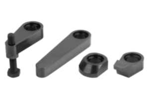
Floating clamp QT steel black nitrocarburized and oxidized 04423-081012
- Simultaneous clamping and supporting of overhanging clamping points on components
- Prevents vibrations and bending
- Low-warp clamping
Sales unit
$736.49 / Piece
plus sales tax
Added to Your Shopping Cart
Designation
Floating clamp
style
A
Style definition
fixed jaw plate
Main
material
QT steel
Surface finish
body
nitrocarburized and oxidized
Main
color
black
Component
material
aluminum
Component
color
black anodized
B=Width
36,5
L=Length
75
SW=key width
13
A
55
B1
26
B2
16,5
B3
9
B4
8,5
Clamping
force
N
5000
D
for screw
M8
D1
10,5
H
max.
80
H
min.
70
H1
24
H2
35
H3
11,5
H4
12
H5
9,3
Load
capacity
N
5000
M
17,3
Steel code
1.0503
Travel
S
12
max.
clamping
travel
12
~ CONFLICT MINERALS 3TG status
no intentional 3TG
~ CP65 substance 1 cancer & reproductive toxicity
lead and lead compounds
~ CP65 substance 2 cancer
soots, tars, and mineral oils
~ PFAS free?
yes
~ REACH SVHC-free?
yes
~ REACh SVHC 2 name > threshold
previous lead possible
~ RoHS conformity
yes, without exemption
~ TSCA 6(H) conformity
yes
Description
Material
Body and jaw steel.
Limit stop aluminum.
Limit stop aluminum.
Version
Body black oxidized.
Jaws nitrocarburised and black oxidized.
Limit stop black anodized.
Jaws nitrocarburised and black oxidized.
Limit stop black anodized.
Note
The floating clamp is used to clamp and support overhanging clamping points on components. It prevents vibrations and deflection during machining.
Method of operation
1. Push the floating clamp down.
2. Pivot the jaws up to the stop. Now the floating jaw of the floating clamp should rest against the underside of the workpiece.
3. Tighten the floating clamp with the hex nut (observe the min. and max. tightening torque). During clamping, the workpiece is clamped and simultaneously supported.
4. To release, perform the procedure in reverse order.
Assembly
Set the height range and the pivot range, then attach the floating clamp to the bracket using the holes (D1).
When setting the height, a generous allowance above should be taken into account.
style B:
For special clamping applications, the standard jaw plate can be modified or replaced.
When setting the height, a generous allowance above should be taken into account.
style B:
For special clamping applications, the standard jaw plate can be modified or replaced.
Drawing reference
1) Exchangeable jaw
2) M6 ISO 4762 cap screw
3) Fastening point for jaw plate
2) M6 ISO 4762 cap screw
3) Fastening point for jaw plate
Important note on downloading CAD models
In order to download our CAD models, you must log in first. If you have not created an account yet, please register under "My Account" (right side of the screen) and follow the instructions.
Other customers also bought