{"product":{"productId":"agid.18306","price":29.01,"name":"BALL LOCK PIN WITH T-GRIP, D1=5, L=10,L1=5,9, L5=15,9, STAINLESS STEEL,COMP:THERMOPLASTIC BLACK GRAY RAL7021"},"currency":"USD"}
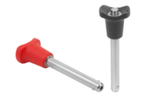
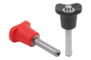
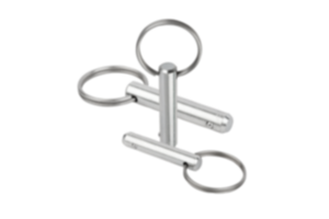
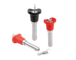
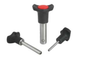
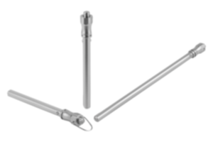
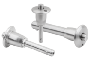
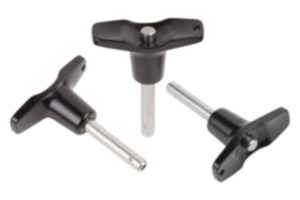
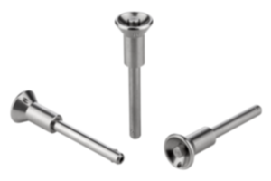
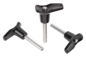
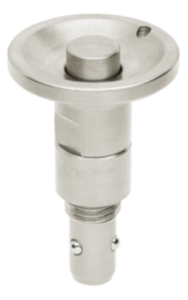
Ball lock pin
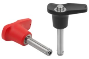
with T-grip
stainless steel
- For connecting machine parts and workpieces quickly and easily
- Application sectors: chemical or foodstuff industries, aerospace industry
- Secure locking by simply pressing and releasing the push button
- Easy to operate
Sales unit
$29.01
plus sales tax
Added to your shopping cart
D1=Pin diameter
5
L=Length
10
B
17,6
Component
color
black gray RAL 7021
Component
material
thermoplastic
D
46
D2
5,5
D3
13,2
Item
Ball lock pin
L1
5,9
L2
25
L3
19,4
L5
15,9
Main
material
stainless steel
Receiving
hole
H11
5
Shearing force
double shear
max.kN
15
Version 1
with T-grip
ball lock pin
grip
t-ročaj širok dolg
Description
Material
Grip thermoplastic.
Steel parts stainless steel 1.4305.
Version
Grip black gray or traffic red RAL 3020.
Stainless steel bright.
Stainless steel bright.
Note
Ball lock pins are used for easy fastening or joining of components or workpieces.
The two balls are disengaged by pressing the push button and the pin can be slipped into holes in the workpieces. When the push button is released, the balls lock the connection securely. If required, the ball lock pins can be fitted with a retaining cable.
Shear force double shear (F) = S · τ aB max.
The values given for the shear force are the theoretical breaking load.
These are non-binding reference values without consideration of safety factors and exclude any liability. The values given are for information purposes only and do not constitute a legally binding assurance of properties.
The load values have been calculated in accordance with DIN 50141. Each user must determine individually whether the ball lock pin is suitable for the respective application.
Different materials in which the ball lock pins are used, weather conditions and wear can influence the determined values.
Accessory
Locating bushings for ball lock pins 03197
Safety spiral cable 03199
Retaining cable with loop 03199
Key ring 03199
Safety spiral cable 03199
Retaining cable with loop 03199
Key ring 03199
Important note on downloading CAD models
In order to download our CAD models, you must log in first. If you have not created an account yet, please register under "My Account" (right side of the screen) and follow the instructions.


